Collect
 Navigate:
SLA7032M and SLA7033M 세減栗죕섟괩송(맒PDF匡도)
DATASHEET PDF 7032.pdf
⊆Outline
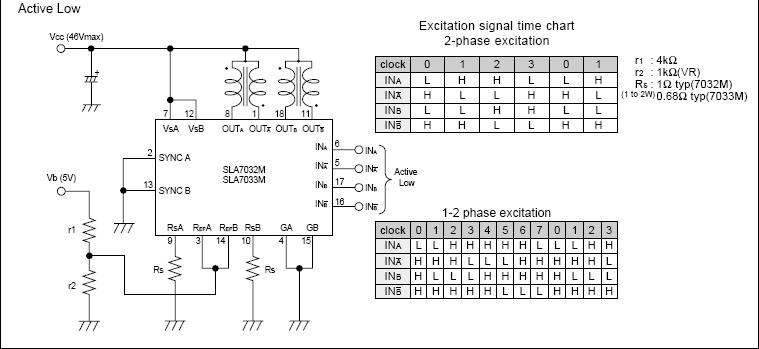
SLA7032M (SLA7033M) is a stepper motor driver IC developed
to reduce the number of external parts required by the conven-
tional SLA7024M (SLA7026M). This IC successfully eliminates
the need for some external parts without sacrificing the features
of SLA7024M (SLA7026M). The basic function pins are com-
patible with those of SLA7024M (SLA7026M).
⊆Notes on Replacing SLA7024M (SLA7026M)
SLA7032M (SLA7033M) is pin-compatible with SLA7024M
(SLA7026M). When using the IC on an existing board, the fol-
lowing preparations are necessary:
(1) Remove the resistors and capacitors attached for setting
the chopping OFF time. (r3, r4, C1, and C2 in the catalog)
(2) Remove the resistors and capacitors attached for preventing
noise in the detection voltage VRS from causing malfunction-
ing and short the sections from which the resistors were re-
moved using jumper wires. (r5, r6, C3, and C4 in the catalog)
(3) Normally, keep pins 2 and 13 grounded because their func-
tions have changed to synchronous and asynchronous
switching (SYNC terminals). For details, see "Circuit for Pre-
venting Abnormal Noise When the Motor Is Not Running (Syn-
chronous circuit)." (Low: asynchronous, High: synchronous)
⊆Circuit for Preventing Abnormal Noise When the
Motor Is Not Running (Synchronous Circuit)
A motor may generate abnormal noise when it is not running. This
phenomenon is attributable to asynchronous chopping between
phases A and B. To prevent the phenomenon, SLA7032M
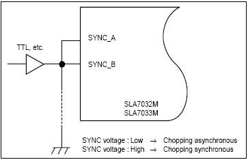
(SLA7033M) contains a synchronous chopping circuit. Do not leave
the SYNC terminals open because they are for CMOS input.
Connect TTL or similar to the SYNC terminals and switch the
SYNC terminal level high or low.
When the motor is not running, set the TTL signal high (SYNC
terminal voltage: 4 V or more) to make chopping synchronous.
When the motor is running, set the TTL signal low (SYNC terminal
voltage: 0.8 V or less) to make chopping asynchronous. If chop-
ping is set to synchronous at when the motor is running, the motor
torque deteriorates before the coil current reaches the set value.
If no abnormal noise occurs when the motor is not running,
ground the SYNC terminals (TTL not necessary).
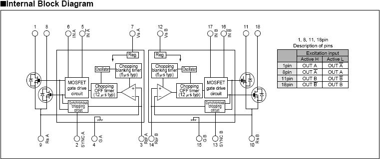
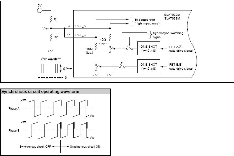
The built-in synchronous chopping circuit superimposes a trigger
signal on the REF terminal for synchronization between the two
phases. The figure below shows the internal circuit of the REF
terminal. Since the ?VREF varies depending on the values of R1
and R2, determine these values for when the motor is not run-
ning within the range where the two phases are synchronized.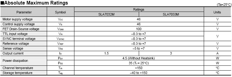


Pre:SLA7060M-SLA7061M-SLA7062M-SLA7065M-SLA7066M-SLA7067M 2026-05-08
Next:SLA7052M 세減栗죕섟괩송(맒PDF匡도) 2026-05-08