Collect
Industrial
 NavigateȤ
The principle of sensor misoperation caused by noise
The principle of sensor misoperation caused by noise
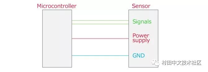
The One chip sensor is mainly composed of three lines of signal, power supply and GND. The signal line is communicated using multiple lines such as clock and data. Consider the effect of each line after noise is applied.
Apply noise to the digital signal line
When noise is applied to the digital signal line, if the noise exceeds the high/low threshold and is misjudged, communication cannot be performed normally and an erroneous operation occurs.
Actually, the noise is added to the digital signal line of the acceleration sensor to confirm that the communication will stop.

Apply noise to the power line
The analog front end includes an amplification circuit and an A/D conversion circuit. When the power supply of these circuits does not work normally, an abnormal value is output and a misoperation occurs.
Actually, the noise is added to the power line of the acceleration sensor to confirm that the output will be disordered.
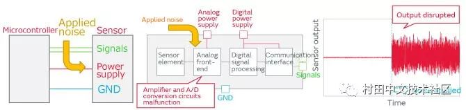
As described above, when noise is applied to the signal line or the power line of the One chip sensor, communication may be stopped or the output value may be erroneously operated.
Key points of sensor noise countermeasures
gist
The filter used for sensor noise suppression measures is required to satisfy the following conditions.
Àþ Power or signal lines required to operate through the device
Àþ Shielding noise that causes misoperation
There are many types and names of One Chip sensors, and the filters required to cause erroneous noise are also different.
This is because the two conditions required for the filter are in communication with the sensor.
Àþ Power supply or signal line required to work through the equipment
˼ One Chip sensor interface (IC lead) is unified
Àþ Shielding noise that causes misoperation
˼The applied noise is within the immunity test specification
Filter placement position
The placement of the filter works well near the sensor.
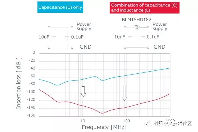
Power line noise suppression countermeasures
The noise suppression countermeasures of the power line are suitable for filters with large insertion loss from a wide bandwidth of low frequency to high frequency.
In the case of using only capacitors, a large-capacity capacitor at the low frequency end and a low-ESL capacitor for obtaining high-frequency insertion loss are required.
In the case of a combination of a capacitor and an inductor, the insertion loss can be significantly increased. The sensor is configured with a sufficient capacity than the inductor to form a multi-segment structure that forms an effective squelch filter.
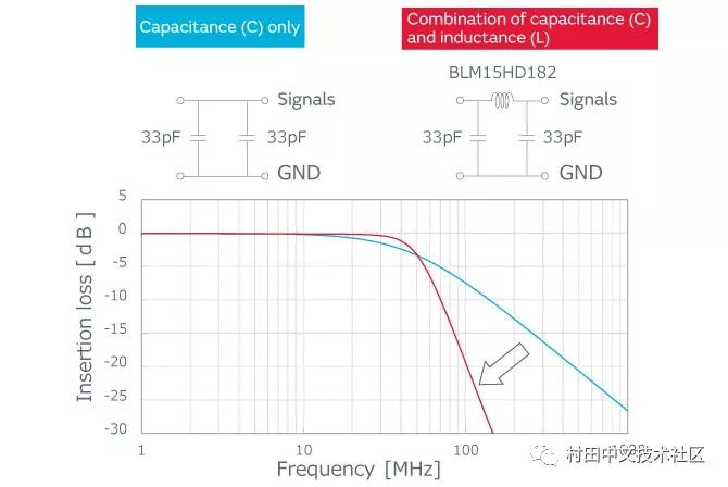
Signal line noise suppression countermeasure
As a countermeasure against noise suppression of a signal line (data/clock), the passing signal requires a filter with a small insertion loss.
When the noise level is small or the frequency of the signal and the noise are large, the noise reduction can be performed only by the capacitor. However, if the signal frequency and the noise frequency are close, a combination of the inductor and the capacitor is required to constitute a filter with a steep insertion loss.
Key points when using the inductor
When the inductor is inserted into a specific line, the line becomes unbalanced and is converted into the normal mode (potential difference), and the erroneous operation may be further deteriorated. An important point when inserting an inductor is that the same product name is used throughout the line.
˻ Ferrite beads are inductive filters that not only have high impedance to block noise, but also ferrite can absorb noise energy for better noise suppression.
@ÇÍäÿøóæ¼ùª