Collect
Industrial
 NavigateŁş
How to measure the Hall sensor
Hall sensor measurement method
1. Good or bad detection of single-pole switching Hall element
The single-pole switching Hall element is energized by 5V, and the output terminal is connected in series. When the magnet is away from the switching Hall element, the output voltage of the switching Hall element is high level (+5V). When the magnet is close to the switch Haller element, the switch The output voltage of the Hall element is low (+0.2V or so), which means that the switch-on Hall element is good. If you do not recognize or leave the Hall switch, the output level of the Hall switch remains unchanged, indicating that the Hall switch is damaged.
2. Good or bad detection of bipolar latched Hall switching components
When the N or S pole of the magnet is close to the Hall switch, the output is high or low, then the Hall element is removed, the level remains unchanged, and the opposite polarity is used to get the opposite level. When the Hall element is good, if the Hall element is close to the obtained level, it will not be latched after the magnet leaves, indicating that the Hall is bad. When the magnet is close to the Hall with the opposite polarity, it is not available. The other polarity is close to the Hall and the opposite level is obtained, then the Hall switch is also bad.
Hall current sensor measurement method
1. The primary side conductor should be placed in the center of the sensor hole.
2. The primary side wire should be completely filled with the sensor inner hole as much as possible, and no gap is left;
3. The current to be measured should be close to the standard IPN of the sensor. Do not differ too much. If the conditions are limited, there is only one sensor with a high rated value, and the current value to be measured is lower than the rated value. In order to improve the measurement accuracy, the primary side wire can be wound a few times to make it close to the rated value. For example, when measuring a current of 10 amps with a sensor with a rating of 100 amps, the primary side conductor can be wound around the center of the inner hole of the sensor for ten times in order to improve the accuracy (generally, NP = 1; one turn in the inner hole, NP=2;......; around nine turns, NP=10, then NPˇÁ10A=100A is equal to the rated value of the sensor, which can improve the accuracy);
4. When the current value to be measured is IPN/10, it can still have higher precision at 25 ˇăC.
Hall sensor measurement steering method
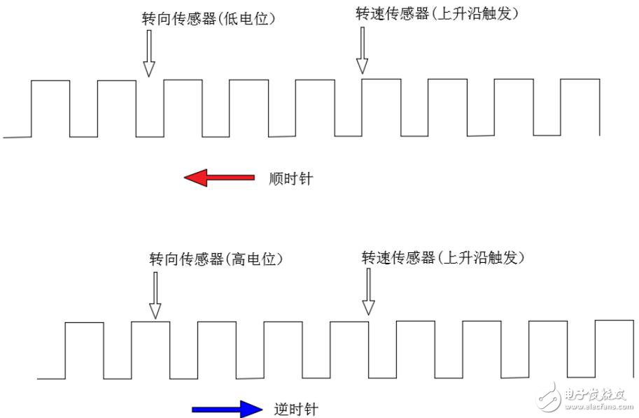
In a general rotating part, a Hall sensor can be used to measure the rotational speed, such as the rotational speed of the engine. There is a ring of teeth on the flywheel of the engine. When each tooth passes through the Hall sensor, it will cause a change in the magnetic induction intensity. This change in the magnetic induction intensity can be converted into a voltage change, and the counter can measure the rotation speed by counting.
Then the problem comes, the counter can tell you the speed, but can't tell you the direction of rotation, how to measure the forward and reverse of the flywheel? See the figure below. There are two Hall sensors, one for measuring the speed and the other for measuring the steering. The Hall sensor that measures the speed is triggered by the rising edge. When the speed sensor triggers the interrupt, the potential of the steering sensor is checked. If the steering sensor is at a low level, it is judged to be clockwise (determined according to the actual situation); if the speed sensor triggers the interruption When the steering sensor is at a high potential, it is counterclockwise.
PreŁşKnow these points to get the right sensor 2026-06-17
NextŁşWhat is a Hall sensor? What mysterious role does it play in the phone? 2026-06-17