Collect
Industrial
 Navigateㄩ
Differential Hall Effect Sensors: Make future two-wheeler applications safer and more reliable
In two- and three-wheeled vehicle applications, the use of electronic devices that control engine, transmission and wheel speed is growing rapidly, especially in developing countries. This trend is driven primarily by demands to improve global air quality, fuel efficiency and vehicle safety.
The control of these systems requires reliable magnetic sensors and targets that can operate in harsh environments where a common challenge is the presence of common mode noise and stray field disturbances caused by the motor and coils during vehicle operation. Wear and damage to the gears and the incorporation of iron scraps into the target wheel can result in reduced or lost control signals.
Two common sensor types used in vehicle control are single-hall and differential Hall-effect sensors. Although single Hall effect sensors can be used, differential Hall effect sensors provide an excellent solution for the following system reliability challenges.
Single Hall vs. Differential Hall Effect Sensor
The signal generated by the single Hall effect sensor is related to the shape of the target tooth/valley, with the peak field level being the best when the target tooth profile is relatively large. The baseline of the signal depends on the pitch and magnet design and may drift or drift as the air gap and gear size change. The result is often reflected in the reduced edge accuracy that is important for engine timing control (Figure 1. To mitigate these effects) A complex magnet system is required to provide a near zero baseline field. Another approach is to add complex circuitry to the sensor design to minimize and correct for bias or drift.
In some basic two- and three-wheel vehicle applications, these sensors have been successfully used in basic engine or transmission control systems, and a growing trend is that certain models are having higher levels of electrification, including engine timing and Transmission control. In these applications, single Hall effect sensors typically lack stray field and noise suppression capabilities and therefore cannot meet newer vehicle requirements.
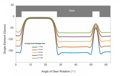
Figure 1: Single Hall Effect Sensor
A single Hall effect sensor can detect large target wheels, and attention should be paid to the deviation offset of narrow target wheels.
The differential Hall effect sensor provides a signal for edge sensing on the target tooth/valley. The signal shape is roughly sinusoidal, up to twice the peak-to-peak magnetic field (Figure 2).
The deviation of the differential signal can be compensated, and the differential signal used is symmetric with respect to zero Gauss. Thus the differential magnet system can be a simple magnet with a high common mode magnetic field, which helps to improve overall air gap performance compared to a single Hall effect sensor.
Differential Hall-effect sensors and their associated signal processing circuits provide excellent immunity to interference and common-mode rejection for noise and stray fields. Baseline drift due to mounting tolerances or air gap changes can be reduced by subtraction and offset reduction circuitry. The combination of these technologies provides the vehicle with the required performance and reliability, enhanced electrification and complex engine timing and gearbox control. In addition, the edge detection capabilities of these sensors make them useful for a variety of target geometries, especially for small target wheels in most two-wheeled vehicle applications.
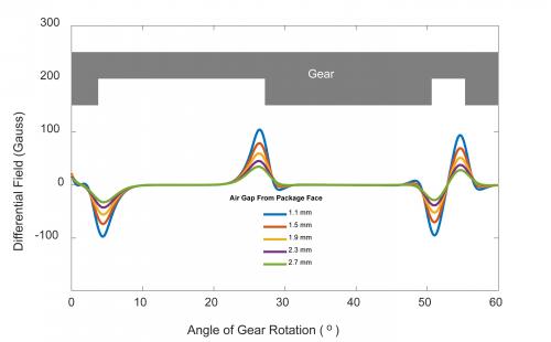
Figure 2: Differential Hall Effect Sensor
The differential Hall effect sensor is capable of detecting the target edge and the target feature has no offset.
Anti-stray field ability
Stray fields generated by alternating current (AC) and direct current (DC) can exist in vehicle powertrains and control systems, which is a significant challenge for speed or direction sensing. Single Hall effect sensors cannot compensate or suppress DC and AC stray fields. In Figure 3, the horizontal dashed line indicates the device switching point levels (for example, 625 G and 635 G), and the output can be switched without stray field conditions. In the presence of a DC stray field, the signal drift caused by the DC stray magnetic field causes the magnetic field level to drift out of the switching point threshold, resulting in no switching and output flat lines. Similarly, if there is an AC stray field, the noise is not adequately suppressed and the device "jitters" around the noise frequency, as shown by the output switching waveform (Figure 3). This increased noise can cause system control and timing errors that can affect vehicle reliability and performance.
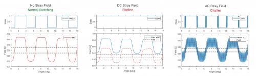
Figure 3: Effect of stray field interference on a single Hall effect device.
Single Hall effect sensors do not adequately eliminate or suppress stray field interference.
A solution that mitigates the effects of stray magnetic fields and reduces or eliminates AC and DC interference signals is a differential Hall effect sensor. The differential configuration and circuitry eliminates the common mode field applied to the sensor Hall probe. Allegro's unique differential architecture further enhances sensor performance and stability against external disturbances.
Figure 4 shows a comparison between normal operation and the presence of AC and DC stray field interference. In the presence of a DC stray field, the upper two traces show the DC field applied to each Hall effect element and the lower trace is the subsequent differential output, which shows the effect of eliminating and maintaining the baseline close to zero Gauss. In the AC stray field example, AC common mode noise is applied to each Hall effect element, and a clean differential output (lower trace) can be obtained due to sensor differential input and common mode noise cancellation (suppression). Signal integrity and proper output switching are maintained in both stray fields. In addition, the differential Hall effect sensor can simultaneously handle both DC and AC.
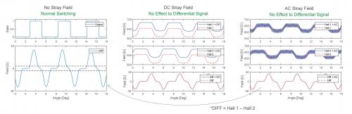
Figure 4: Effect of stray field interference on differential Hall effect devices.
Differential Hall effect sensors eliminate and suppress stray field interference.
Ability to withstand installation tolerances
Although the operation of a single Hall effect sensor is independent of the mounting direction, positional changes may occur after installation, which may cause offset and signal amplitude reduction. Figure 5 shows the possible sensor displacements that cause deviations from the absolute (installation) values, resulting in a DC offset. Figure 6 exemplifies that the deviation can cause the signal level to drop below the switching threshold (dashed line), resulting in no switching and output flat lines.
By using a differential sensor, any offset due to changes in mounting position can be eliminated and the baseline is kept close to zero Gauss. This ensures that the signal remains within the device switching threshold, allowing for normal switching regardless of position (Figure 7).
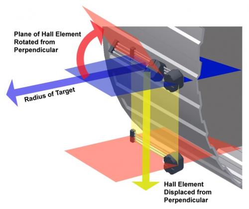
Figure 5: The orientation of the Hall effect sensor for the target.
Possible position changes after installation.
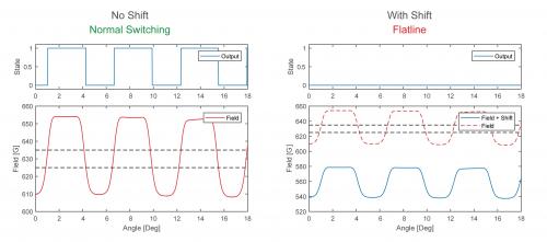
Figure 6: Effect of the offset caused by the installation on the single Hall effect sensor.
Single Hall effect sensor is prone to output flat line, no switching
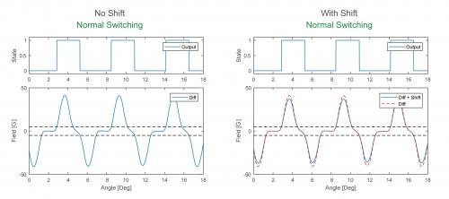
Figure 7: Effect of the offset caused by the installation on the differential Hall effect sensor.
The differential Hall effect sensor maintains normal output switching.
Ability to resist sudden air gap changes
"Sudden" refers to the change in air gap from one target feature (gear tooth and valley) to the next target feature, and this change is not part of the normal feature of a given target wheel. For example, a sudden change in air gap may be caused by damage caused by bending or missing teeth or by intrusion of iron objects and debris into the surface of the target wheel. Figure 8 shows an example of a correlated magnetic field signal produced by a single Hall effect sensor and a differential Hall effect sensor due to a reduction in the target wheel air gap due to tooth bending.
When a single Hall effect sensor is used, the air gap variation causes the offset offset and amplitude variation to exceed the switching threshold (dashed line). Once the signal reaches this point, the sensor stops switching and outputs a flat line.
The differential Hall effect sensor eliminates the offset offset and measures the change in signal amplitude, with the resulting signal maintaining the baseline close to zero Gauss. This enables the signal to be within the device switching threshold, ensuring that the device continues to provide output switching without being affected by bias offset and air gap reduction.
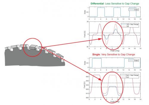
Figure 8: Effect of the offset caused by a sudden air gap change on the Hall effect sensor.
Single Hall effect sensors are very sensitive to air gap changes, and differential Hall effect sensors are less sensitive to air gap changes.
Ability to resist dynamic air gap changes
A gradual or abrupt air gap change can occur as the target wheel rotates, resulting in a dynamic air gap change. This discontinuity is generally consistent for each revolution of the target wheel, and the end result is that the change in signal amplitude reflects multiple target wheel signal characteristics. In this case, the sensor is required to be able to adapt appropriately to the changing signal so that switching can continue.
For two- and three-wheel vehicle applications, one form of air gap dynamic change is the target wheel bounce or swing. Bounce is an air gap change associated with each rotation of the target wheel and occurs progressively (on multiple teeth) as shown in FIG. Some common causes include shaft position eccentricity, target wheel eccentricity, target wheel damage/warping, or other loads on the shaft/bearing.
Total effective air gap (TEAG)
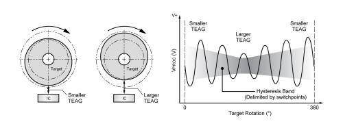
Figure 9: Effect of the bounce/swing on the total effective air gap (TEAG).
When a single Hall effect sensor is used to pulsate or oscillate, by measuring deviations and amplitude changes, the signal may fall below the switching point threshold and be lost, causing the speed pulse to be lost (Figure 10), resulting in a system error or malfunction.
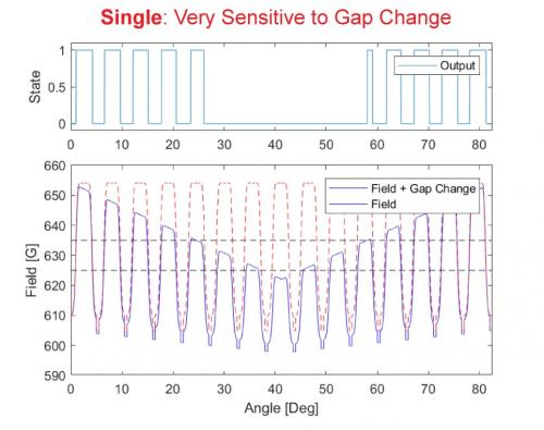
Figure 10: Effect of bounce/swing on a single Hall effect sensor.
Single Hall effect sensors are very sensitive to air gap changes.
The differential Hall-effect sensor eliminates skew and prevents baseline skew (Figure 11), keeping the signal at the center of the device switching point threshold, allowing for proper switching even in the event of a signal change.

Figure 11: Effect of the bounce/swing on the differential Hall effect sensor.
Differential Hall effect sensors are less sensitive to air gap variations.
Other ways to improve signal integrity and system performance
The electrification of two- and three-wheeled vehicles will continue to become higher and higher. In order to achieve the safest and most reliable electronic control of the engine, transmission and wheel speed, the differential Hall effect sensor is superior to the single Hall effect sensor. Excellent solution. To further improve signal integrity and system performance, consider the following recommendations:
1. Use a sensor with integrated capacitors in the package to improve EMC performance by reducing the resistance between the capacitor and other device circuits. This approach also reduces the number of auxiliary printed circuit boards (PCBs) that assemble discrete components, thereby reducing overall system cost.
2. The IC and optimized back magnetism integrated package can make the manufacturing simple and have consistent performance and enhanced reliability over the entire temperature range.
3. Use a proven peak detection algorithm with strong anti-jamming capability.