Collect
Industrial
 NavigateŁş
How sensor performance supports state monitoring solutions
Advances in semiconductor technology and capabilities offer new opportunities for industrial applications, particularly state monitoring solutions, to detect, measure, interpret, and analyze data. A new generation of sensors based on MEMS technology combined with advanced algorithms for diagnostic prediction applications expands the opportunity to measure a wide range of machines and increase their capabilities, helping to efficiently monitor equipment, increase uptime, enhance process quality and increase throughput.
To achieve these new capabilities and gain the benefits of condition monitoring, the new solution must be accurate, reliable, and robust so that real-time monitoring can extend beyond basic detection of potential equipment failures, providing insightful and actionable information. The combination of next-generation technology performance and system-level insights helps people gain a deeper understanding of the applications and requirements needed to address these challenges.
Vibration is one of the key elements of machine diagnostics and has been reliably used to monitor the most critical equipment in a variety of industrial applications. There is a wealth of literature to support the various diagnostic and predictive capabilities required to implement advanced vibration monitoring solutions. However, there is not much literature on the relationship between vibration sensor performance parameters (such as bandwidth and noise density) and the ability to diagnose faults in the final application. This article describes the main types of machine failures in industrial automation applications and identifies key performance parameters for vibration sensors associated with a particular fault.
The following highlights several common types of failures and their characteristics to gain insight into some of the key system requirements that must be considered when developing a condition monitoring solution. The types of failures include, but are not limited to, imbalances, misalignments, gear failures, and rolling bearing defects.
unbalanced
What is imbalance and what causes imbalance?
Unbalance means that the mass distribution is uneven, causing the load to cause the center of mass to deviate from the center of rotation. System imbalance can be attributed to improper installation (such as coupling eccentricity), system design errors, component failures, and even the accumulation of debris or other contaminants. For example, the cooling fans built into most induction motors may become unbalanced due to uneven accumulation of dust and grease or damage to the blades.
Why is the imbalance system a problem?
Unbalanced systems can generate excessive vibrations that can be mechanically coupled to other components within the system, such as bearings, couplings, and loads, which can cause accelerated degradation of components in good operating conditions.
How to detect and diagnose imbalances
An increase in overall system vibration may indicate a potential failure caused by an unbalanced system, but the root cause of the increased vibration needs to be diagnosed by frequency domain analysis. The unbalanced system produces a signal at the rate of rotation of the system (commonly referred to as 1ˇÁ), the amplitude of which is proportional to the square of the rate of rotation, F = m ˇÁ w2. The 1 ˇÁ component is usually always present in the frequency domain, so Measuring the amplitude of 1x and harmonics can identify an unbalanced system. If the amplitude of 1ˇÁ is higher than the baseline measurement and the harmonics are much smaller than 1ˇÁ, there is likely to be an unbalanced system. Horizontal and vertical phase shifting vibration components may also occur in unbalanced systems1.
What system specifications must be considered when diagnosing an unbalanced system?
The noise must be low in order to reduce the effects of the sensor and to support the detection of small signals generated by unbalanced systems. This is very important for sensors, signal conditioning and acquisition platforms.
In order to detect small imbalances, the acquisition system needs to have a sufficiently high resolution to extract the signal (especially the baseline signal).
In addition, sufficient bandwidth is needed to capture sufficient information (not just the rate of rotation) to improve diagnostic accuracy and reliability. 1ˇÁ harmonics may be affected by other system faults, such as misalignment or mechanical looseness, so analyzing the harmonics of the rotation rate (or 1ˇÁfrequency) can help distinguish system noise from other potential faults1. For slow rotating machines, the basic rotation rate may be well below 10 rpm, which means that the sensor's low frequency response is critical to capturing the basic rate of rotation. ADI's MEMS sensor technology detects low-to-DC signals and is capable of measuring slower rotating equipment while measuring wide bandwidth for higher frequency content typically associated with bearing and gearbox defects.
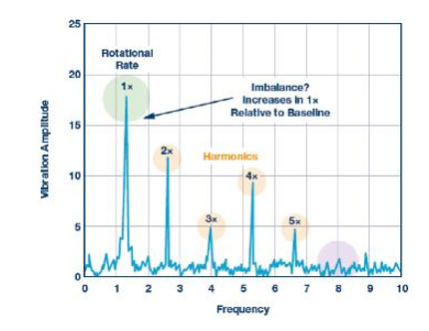
Figure 1. The increase in the rate of rotation or the 1X frequency may mean the presence of an unbalanced system.
Misaligned
What is misalignment and what causes misalignment?
As the name implies, system misalignment occurs when the two rotating axes are misaligned. Figure 2 shows an ideal system where the alignment starts from the motor, then the shaft, the coupling, and all the way to the load (in this case, the pump).
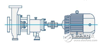
Figure 2. Ideal alignment system
Misalignment can occur in parallel and angular directions, or a combination of both (see Figure 3). When two axes are misaligned in the horizontal or vertical direction, they are called parallel misalignments. When one of the axes is at an angle to the other axis, it is called an angle misalignment 2.
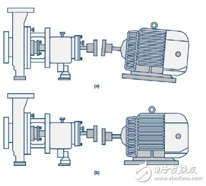
Figure 3. Examples of different misalignments, including (a) angle, (b) parallel, or a combination of both.
Why is misalignment a problem?
Misalignment errors can force components to work under stress or load above the original design capability, affecting larger systems and ultimately leading to premature failure.
How to detect and diagnose misalignment
The misalignment error usually appears as the second harmonic of the system's rate of rotation, called 2x. The 2x component does not necessarily exist in the frequency response, but when it is present, its magnitude relationship with 1x can be used to determine if there is a misalignment. The increased alignment error can excite harmonics to 10x depending on the type of misalignment, measurement position and direction information1. Figure 4 highlights features associated with potential misalignment failures.
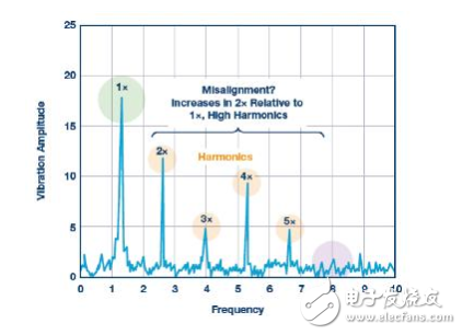
Figure 4. Increasing 2ˇÁ harmonics plus increasing higher harmonics indicate possible misalignment.
What system specifications must be considered when diagnosing misaligned systems?
In order to detect small misalignments, low noise and sufficiently high resolution are required. Machine type, system and process requirements, and rotation rate determine the allowable misalignment tolerance.
In addition, sufficient bandwidth is needed to capture a sufficient frequency range to improve diagnostic accuracy and reliability. 1ˇÁ harmonics may be affected by other system faults, such as misalignment, so analyzing 1ˇÁ frequency harmonics can help distinguish other system faults. This is especially suitable for higher speed machines. For example, in order to accurately and reliably detect imbalances, machines (machine tools, etc.) with a speed of more than 10,000 rpm usually require high-quality information of more than 2 kHz.
The combination of system phase and directional vibration information further improves the diagnosis of misalignment errors. Measuring vibration at different points on the machine and determining differences between phase measurements or throughout the system helps to gain insight into whether misalignment is angle, parallel, or a combination of two misaligned types.
Rolling element bearing defect
What are rolling element bearing defects and what causes them?
Rolling element bearing defects are often the illusion of mechanically induced stress or lubrication problems that create small cracks or defects in the mechanical components of the bearing, resulting in increased vibration. Figure 5 provides some examples of rolling element bearings and shows several possible defects.
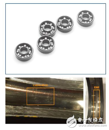
Figure 5. Example of (top) rolling element bearing and (bottom) lubrication and discharge current defects
Why is rolling element bearing failure a problem?
Rolling element bearings are used in almost all types of rotating machinery, from large turbines to slow rotating motors, from relatively simple pumps and fans to high speed CNC spindles. Bearing defects can be signs of lubrication contamination (Figure 5), improper installation, high-frequency discharge current (Figure 5), or increased system load. Failure can result in catastrophic system damage and a significant impact on other system components.
How to detect and diagnose rolling element bearing faults?
A variety of techniques are available to diagnose bearing faults, and due to the physical characteristics behind the bearing design, the defect frequency of each bearing can be calculated based on bearing geometry, rotational speed, and defect type, which helps diagnose faults. The bearing defect frequency is shown in Figure 6.
Analysis of vibration data for a particular machine or system often relies on a combination of time domain and frequency domain analysis. Time domain analysis can be used to detect the overall increase in system vibration levels. However, this analysis contains very little diagnostic information. Frequency domain analysis can improve diagnostic insight, but the frequency of faults can be complex due to the effects of other system vibrations.
For early diagnosis of bearing defects, the use of harmonics of the defect frequency identifies early or emerging faults to monitor and maintain catastrophic failures before they occur. In order to detect, diagnose, and understand the systemic effects of bearing faults, techniques such as envelope detection (shown in Figure 7) combined with spectral analysis in the frequency domain often provide more insightful information.
What system specifications must be considered when diagnosing rolling element bearing faults?
Low noise and high enough resolution are critical for early bearing defect detection. When a defect has just appeared, the magnitude of the defect feature is usually very low. Due to design tolerances, the inherent mechanical slip of the bearing propagates amplitude information to multiple bins in the bearing frequency response, further reducing the amplitude of the vibration, thus requiring low noise to detect signal 2 earlier.
Bandwidth is critical for early detection of bearing defects. During the rotation, each time a defect is struck, a pulse containing high frequency content is generated (see Figure 7). Monitoring these harmonics of the bearing defect frequency (rather than the rate of rotation) reveals these early failures. Due to the relationship between the bearing defect frequency and the rate of rotation, these early features can occur in the range of several kilohertz and extend beyond the range of 10 kHz to 20 kHz2. Even for low-speed equipment, the inherent nature of bearing defects requires a wider bandwidth for early detection of defects, avoiding system resonances and system noise (which can affect lower frequency bands).
Dynamic range is also important for bearing defect monitoring because system loads and defects can affect the vibrations experienced by the system. An increase in load causes an increase in the force acting on the bearings and the defects. Bearing defects can also create shocks that excite structural resonances and amplify the vibrations experienced by the system and the sensor 2 . As the speed of the machine rises and falls during stop/start or during normal operation, the speed of change creates a potential opportunity for system resonance excitation, resulting in higher amplitude vibrations4. Saturation of the sensor can result in loss of information, mis-diagnosis, and in some cases even damage to the sensor element.
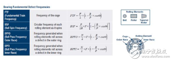
Figure 6. Bearing defect frequency depends on bearing type, geometry and rotation rate.
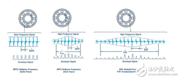
Figure 7. Techniques such as envelope detection can extract bearing early defect features from wide bandwidth vibration data.
Gear defect
What is a gear defect and what causes a gear defect?
Gear failures typically occur in the toothed joints of the gear mechanism due to fatigue, spalling or pitting. It appears as a crack in the root or a metal on the tooth surface is removed. Causes are wear, overload, poor lubrication and backlash, and occasionally due to improper installation or manufacturing defects.
Why is gear failure a problem?
Gears are the main component of power transmission in many industrial applications, subject to considerable stress and load. The health of the gears is critical to the proper functioning of the entire mechanical system. A well-known example in the field of renewable energy, the biggest factor contributing to wind turbine downtime (and corresponding revenue loss) is the failure of multi-stage gearboxes in the main power system. Similar considerations apply to industrial applications.
How to detect and diagnose gear faults?
The detection of gear faults is tricky due to the difficulty in installing the vibration sensor near the fault and the considerable background noise caused by various mechanical excitations within the system. This is especially true in more complex gearbox systems where there may be multiple rotational frequencies, gear ratios and meshing frequencies of six. Therefore, detecting gear failures may involve a variety of complementary methods, including acoustic emission analysis, current characterization, and oil slag analysis.
In terms of vibration analysis, the accelerometer is usually mounted on the gearbox housing and the main vibration mode is axial vibration 7. The frequency of the vibration characteristic produced by the healthy gear is the so-called gear meshing frequency, which is equal to the product of the shaft frequency and the number of gear teeth. There are also some modulation sidebands associated with manufacturing and assembly tolerances. These conditions of the health gear are shown in Figure 8. When a local fault such as a tooth crack occurs, the vibration signal in each revolution will include the mechanical response of the system to a short-term impact of a relatively low energy level. This is usually a low amplitude wideband signal and is generally considered to be non-periodic and non-static 7,8.
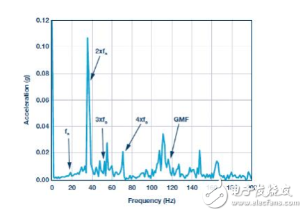
Figure 8. The spectrum of the healthy gear, with a crankshaft speed of ~1000 rpm, a gear speed of ~290 rpm, and a gear count of 24.
Due to these characteristics, gear failures cannot be accurately identified by standard frequency domain techniques alone. Since the impact energy is included in the sideband modulation, which may also include energy from other gear pairs and mechanical components, spectral analysis may not be able to detect early gear failures. Time domain techniques (such as time-synchronized averaging) or mixed-domain methods (such as wavelet analysis and envelope demodulation) are generally more appropriate.
What system specifications must be considered when diagnosing gear failures?
In general, wide bandwidth is important for gear fault detection because the number of gear teeth is a multiplier in the frequency domain. Even for relatively low speed systems, the required detection frequency range quickly rises to the kHz region. In addition, local failures further extend bandwidth requirements.
Resolution and low noise are critical for a variety of reasons. It is difficult to mount the vibration sensor near a specific fault area, which means that the mechanical system may cause a high degree of attenuation of the vibration signal, so it is important to be able to detect low energy signals. Furthermore, since the signal is not a static periodic signal, it cannot rely on standard FFT techniques for extracting low amplitude signals from high noise floor, and the noise floor of the sensor itself must be low. This is especially true in gearbox environments where multiple vibrational features of different components are mixed. In addition to these considerations, the importance of early detection is not only for asset protection reasons, but also for signal conditioning reasons. It has been shown that the case of a single tooth breakage is more severe than the case of two or more tooth breaks, which means that the early detection may be relatively easier.
Conclusion
Although common, imbalances, misalignments, rolling element bearing defects, and gear toothing failures are just a few of the many types of failures that high-performance vibration sensors can detect and diagnose. The combination of higher sensor performance and appropriate system-level considerations enables a new generation of condition monitoring solutions that give people a deeper understanding of the mechanical operation of various industrial equipment and applications. These solutions will change the way maintenance is performed and how the machine behaves, ultimately reducing downtime, increasing efficiency, and enabling new generations of equipment with new capabilities.
PreŁşWhat are the characteristics of sensor technology? 2026-06-11
NextŁşWhy earthquake warning can beat the earthquake wave 2026-06-11