Collect
Industrial
 NavigateŁş
Eddy Current Sensor
There are a variety of sensors, and there are many that we can choose from. Many high-performance sensors such as inductive eddy current sensors are widely used in various industries. In particular, the machine tool industry, as well as the automobile manufacturing industry, are widely used, and are recognized as high-tech industries with promising future.
Eddy current sensor working principle
Eddy current effect: The eddy current sensor works according to the eddy current effect, that is, the metal conductor is placed in a changing magnetic field to generate an induced current, thereby forming a self-closing eddy current line in the metal body. This phenomenon is called eddy current. effect.
Eddy current sensor structure and characteristics
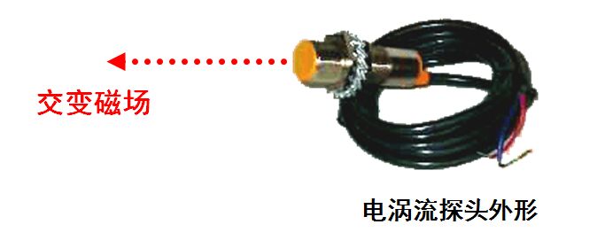
Sensing Element - Eddy Current Probe: The eddy current probe is a flat coil fixed to the frame with a high excitation frequency (tens of kilohertz to several megahertz).
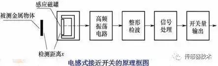
There is a small coil in the sensor probe, which is controlled by the controller to generate an oscillating electromagnetic field. When approaching the object to be measured, an induced current is generated on the surface of the object to be measured, and a reverse electromagnetic field is generated. At this time, the eddy current sensor judges the distance from the object to be measured based on the strength of the reverse electromagnetic field. Note: The eddy current sensor requires that the measured object be a conductor.
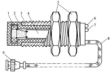
1ˇŞElectro-vortex coil 2ˇŞProbe housing 3ˇŞPosition adjustment thread on the housing
4ˇŞPrinted circuit board 5ˇŞClamping nut 6ˇŞPower indicator
7ˇŞThreshold indicator light 8ˇŞOutput shielded cable 9ˇŞCable plug
History of eddy current displacement sensor measurement technology
The first to discover the phenomenon of eddy currents was François Arago (1786¨C1853), the 25th French president, mathematician, physicist and astronomer. In 1824, he first discovered and named the rotating magnetic field, and most of the conductors could be magnetized. His findings were later compiled and refined by Michael Faraday (1791¨C1867).
In 1834, Heinrich Lenz issued Lenz's law, in which the induced current has a direction in which the magnetic field of the induced current always obstructs the change in the magnetic flux that causes the induced current.
The French physicist L¨¦on Foucault (1819¨C1868) discovered in 1855 that the force required to rotate a copper disk was greater in the middle of the magnetic field. At the same time, the copper disk was internally induced by eddy currents. And fever.
In 1879, David E. Hughes pioneered the use of eddy current technology for non-contact measurement for sorting metal objects.
In 1980, the German rice bran company took the lead in the use of eddy current displacement sensors for industrial production testing.
In 1988, the German rice bran company released the world's smallest eddy current displacement sensor, so that in the case of limited installation space, the eddy current principle can also be used to obtain accurate measurement data.
Advantages of eddy current sensors
1. The eddy current sensor is a non-contact linearization measuring tool that can measure the distance of the metal conductor to be measured from the surface of the probe statically and dynamically without contact, high linearity and high resolution. The measurement accuracy of the eddy current sensor during the measurement process will be affected to some extent.
2. When the sensor characteristics and the conductivity of the measured body, due to the simultaneous eddy current effect and magnetic effect, the magnetic effect reacts to the eddy current effect, so that the eddy current effect is weakened, that is, the sensitivity of the sensor is lowered. When the measured body is a weak magnetic conductive material (such as copper, aluminum, alloy steel, etc.), since the magnetic effect is weak, the eddy current effect is relatively strong, so the sensor sensitivity is high.
3. Irregular surface of the measured object will bring additional error to the actual measurement. Therefore, the surface of the measured object should be smooth and smooth, and there should be no defects such as protrusions, holes, nicks and grooves. Generally, the measured surface roughness of the vibration measurement is required to be between 0.4um and 0.8um; for the displacement measurement, the measured surface roughness is required to be between 0.4um and 1.6um.
4. The eddy current effect is mainly concentrated on the surface of the measured object. If the residual magnetic effect is formed during the processing, the quenching is uneven, the hardness is not uniform, the metallographic structure is uneven, and the crystal structure is uneven, etc., the sensor characteristics are affected. When the vibration measurement is performed, if the surface residual effect of the measured object is too large, the measurement waveform may be distorted.
Classification of eddy current sensors
According to the penetration of the eddy current in the conductor, the sensor can be divided into two types: high frequency reflection type and low frequency transmission type, but the basic working principle is still similar.
High frequency reflective eddy current sensor
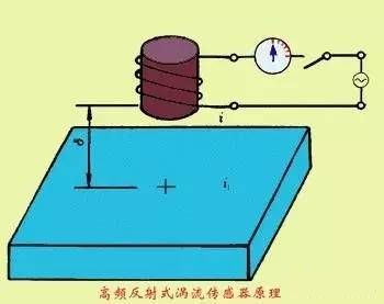
The high frequency (>lMHz) excitation current, the generated high frequency magnetic field acts on the surface of the metal plate, and an eddy current will be formed on the surface of the metal plate due to the skin effect. At the same time, the alternating magnetic field generated by the eddy current reacts to the coil, causing the change of the coil self-inductance L or the impedance ZL, the change and the distance, the resistivity ¦Ń of the metal plate, the magnetic permeability ¦Ě, the excitation current i, and the angle The frequency ¦Ř is related. If only the distance ¦Ä is changed and the other coefficients are kept unchanged, the change of the displacement can be converted into a change in the self-inductance of the coil, and converted into a voltage output by the measuring circuit. High-frequency reflective eddy current sensors are mostly used for displacement measurement.
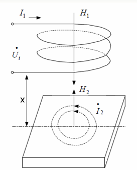
Low frequency transmissive eddy current sensor
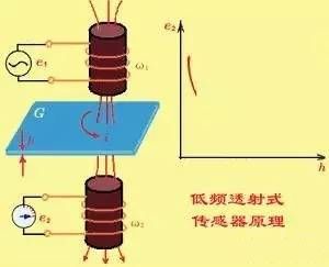
Low frequency transmission eddy current sensors are mostly used to determine material thickness. The transmitting coil W1 and the receiving coil W2 are respectively placed above and below the material G to be measured, and after the low-frequency voltage e1 is applied to both ends of the coil W1, an alternating magnetic field is generated in the surrounding space, and a vortex i is generated in the material G to be measured. The eddy current loses part of the energy, reducing the magnetic flux passing through W2, thereby reducing the induced potential e2 generated by W2. The size of e2 is related to the thickness of G and the material properties. Experiments show that e2 decreases with the increase of material thickness h according to the negative exponential law. Therefore, the thickness of the material can be measured by the change of e2.
Measuring circuit of eddy current sensor
When measuring with an eddy current conversion element, in order to obtain a strong eddy current effect, the excitation coil usually operates at a higher frequency, so the signal conversion circuit mainly has two types of amplitude modulation circuits and frequency modulation circuits.
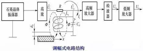
Amplitude modulation (AM) circuit
Frequency modulation (FM) circuit
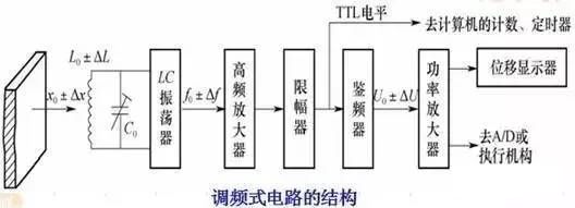
When the distance x between the eddy current coil and the measured object changes, the inductance L of the eddy current coil also changes, causing a change in the output frequency of the LC oscillator, which can be directly measured by a computer.
Application of eddy current sensor
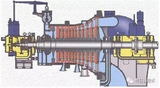
Eddy current sensor systems are widely used in electric power, petroleum, chemical, metallurgical and other scientific research units. Radial vibration, axial displacement, phase shifter, shaft speed, differential expansion, eccentricity, and rotor dynamics of large rotating mechanical shafts such as steam turbines, turbines, blowers, compressors, air separation machines, gearboxes, and large cooling pumps Online measurement and protection, such as part size inspection.
1. Application on industrial equipment
Axial displacement measurement: For many rotating machinery, including steam turbines, gas turbines, hydraulic turbines, centrifugal and axial compressors, centrifugal pumps, etc., axial displacement is a very important signal, too large axial displacement will Causes excessive damage to the mechanism. The measurement of the axial displacement can indicate an axial gap or a relatively instantaneous displacement change between the rotating component and the stationary component to prevent damage to the machine.
Axial displacement refers to the internal rotor of the machine in the axial direction, relative to the gap between the thrust bearings. Some mechanical failures can also be judged by the detection of axial displacement: 1. Wear and failure of the thrust bearing; 2. Wear and failure of the balance piston; 3. Loosening of the thrust flange; 4. Coupling Lock and so on.
The measurement of axial displacement (axial clearance) is often confused with axial vibration. Axial vibration refers to the rapid change of the distance between the surface of the sensor probe and the measured object along the axial direction. This is the vibration of the shaft, expressed by the peak-to-peak value. It has nothing to do with the average gap. Some faults can cause axial vibration. For example, the vibration and misalignment of the compressor is.
Vibration measurement: measuring radial vibration, it can be seen from the working state of the bearing, and the imbalance of the rotor can be seen, which is not suitable for medium mechanical failure. It can provide the information needed for mechanical condition monitoring of the following key or basic machinery: 1, industrial turbine, steam / gas; 2, compressor, air / special purpose gas, radial / axial; 3, expander; 4, power generation turbine, steam / gas / water; 5, electric motor, generator; 6, exciter; 7, gear box; 8, pump; 9, fan, fan; 10, reciprocating machinery.
Vibration measurements can also be used for continuous monitoring of small, general machinery. It provides important information for early identification of various mechanical failures as follows:
1. Synchronous vibration of the shaft, oil film instability;
2, the rotor friction, loose parts;
3. The bearing sleeve is loose and the compressor is vibrating;
4, rolling bearing bearing failure, radial preload, internal / external including misalignment;
5, bearing babbitt wear, bearing clearance is too large, radial / axial;
6, balance (gas barrier) piston wear / failure, the coupling "locked";
7, shaft bending, shaft crack;
8. The air gap of the electric motor is uneven and the gear is engaged.
9. The turbine blade channel resonates and the impeller passes through the phenomenon.
Eccentricity measurement: Eccentricity is the measurement of the degree of bending of the shaft by the eddy current sensor system at low speeds, which can be caused by:
1. The original mechanical bending ˇ¤ The bending caused by the temporary temperature rise ˇ¤ In the static state, there must be some downward bending, sometimes called gravity bending, and bending caused by external force.
2. Eccentric measurement is very important for evaluating the overall mechanical state of a rotating machine. Especially for steam turbines equipped with Turbine Monitoring Instrumentation Systems (TSI), eccentricity measurement has become an indispensable measurement item during start-up or shutdown. It allows you to see the extent of the shaft bending due to heat or gravity. The eccentric position of the rotor, also called the radial position of the shaft, is often used to indicate bearing wear and the amount of load applied. In the case of misalignment, it is also used to determine the azimuth of the shaft. The azimuth can indicate whether the rotor is stable.
Differential pressure measurement
For turbine generator sets, the thermal expansion of the shaft may exceed the expansion of the casing due to the difference in thermal expansion coefficient and heat dissipation during start-up and shutdown, which may cause the rotating parts of the turbine and The contact of stationary components (such as cabinets, nozzles, pedestals, etc.) causes damage to the machine. Therefore, the measurement of the differential expansion is very important.
Speed measurement
For all rotating machinery, it is necessary to monitor the rotational speed of the rotating machine shaft, which is an important indicator of the normal operation of the machine. The superiority of the eddy current sensor in measuring the speed is unmatched by any other sensor measurement. It can respond to both zero speed and high speed, and the anti-interference performance is also very strong.
Rotating measurements usually have the following sensors: eddy current speed sensor, passive magnetoelectric speed sensor, active magnetoelectric speed sensor, etc. If there is a need to select the type of sensor, it is necessary to measure the required speed according to the speed. (The speed generating device has the following types: the standard involute wire number (M1 ~ M5) is used as the speed generating signal, and a keyway is opened on the rotating shaft. In the rotating shaft on the rotating shaft to open the eye, the shaft is turned on the convex key and other speed generating signal device.
Rolling bearing, motor commutator rectifier dynamic monitoring
Predictive maintenance of machines using rolling bearings is important. The probe is mounted in the bearing housing to view the outer ring of the bearing. The outer ring is slightly deformed when the rolling element collides with the bearing where the rolling element is in rotation. The monitoring system can detect this deformation signal. When the signal is deformed, it means that a fault has occurred, such as a crack defect of the rolling element or a defect of the bearing ring. It can also measure the running state of the inner ring of the bearing, and the bearing slip can be measured through calculation.
2. Application of eddy current sensor in coin identification system
With the widespread use of automatic coin-operated machines, some lawless elements in the society have deliberately studied the form and material of existing coins, and in accordance with this, created counterfeit coins that can be faked. These counterfeit coins have entered the market and resulted in automatic coin-operated machines. Normal work, causing economic losses to relevant departments.
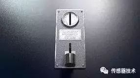
There are many kinds of coins in China, which brings considerable difficulty to the anti-counterfeiting and identification of coins. The main technical problem of coin recognition is the detection method of coins. The core is to detect the performance of sensors.
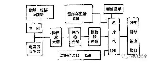
The principle block diagram of the coin identification system is shown in the figure. The basic working process is as follows: when the coin passes through the eddy current sensor, the corresponding eddy current is generated, and the signal conditioning and detection circuit converts the eddy current information into corresponding corresponding signals through appropriate transformation. The digital quantity is used for real-time analysis and processing by the single chip microcomputer. The processing result of the single chip microcomputer is used to control the work of the coin counting control circuit and the sound and light alarm circuit, and complete the task of identifying the coin.
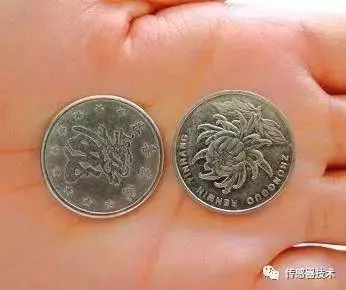
The coin identification system consisting of an eddy current sensor as a detecting element is specifically designed for the metal raw material of a 1-yuan coin currently issued in China.
When a coin enters the path of the slot machine through the coin inlet, the eddy current sensor utilizes a change in magnetoresistance in the magnetic circuit and generates a current in the conductor placed therein, the flow line of which is closed within the metal conductor. (So called eddy current, or eddy current).
This current also produces an alternating magnetic field that blocks the change in the external magnetic field. From the perspective of its energy, because there is an electromagnetic effect in the eddy current loss in the conductor under test, it will generate Joule heat and generate hysteresis loss, resulting in loss of alternating magnetic field energy. The loss of these energies causes the sensor's equivalent reactance, equivalent inductance, and quality factor to change.
If the distance between the sensor and the conductor under test remains the same, the output parameters of the sensor will be a function of the conductivity and permeability of the material being tested. When the distance between the coil and the metal conductor is fixed, the frequency of the sensor output signal is only related to the intrinsic property of the metal conductor material in the magnetic field, that is, the signal frequency is affected by the inductance of the coil.
When the coin is close to the coil, the inductance will change, and the sine wave frequency will also change accordingly. Therefore, the change of the signal frequency reflects the material characteristics of the coin, so the basis for distinguishing between true and false and currency value can be obtained by measuring the frequency of the sensor signal. This relationship can be used to measure the conductivity, permeability and other parameters of metal materials.
These parameters have a certain relationship with the material, geometry and other factors of the conductor. Finding the weak differences caused by the influence of different metal materials and volumes on the system's magnetic field information, these signals are processed by the signal conditioning circuit, and then the intelligent analysis of the collected data by a single-chip microcomputer can complete the metal coins. Identification.
3. Application of eddy current sensor in other fields
Induction cooker
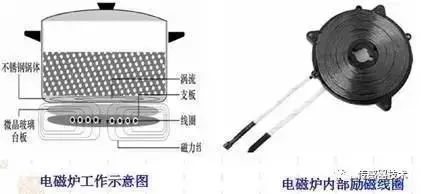
Induction cooker is one of the essential household appliances in our daily life. The eddy current sensor is one of its core components. The high-frequency current passes through the excitation coil to generate an alternating magnetic field. At the bottom of the iron pot, there will be countless eddy currents to make the bottom of the pot. Self-heating, boil the food in the pot.
Eddy current detector

Eddy current proximity switch: Proximity switch is also called contactless travel switch. It can detect the presence of objects close to a certain distance (a few millimeters to tens of millimeters).
When the object approaches a set distance, an "action" signal can be issued. The core part of the proximity switch is the "intelligence head", which has a high ability to sense objects that are approaching. This proximity switch only detects metal.
PreŁşMotor Hall sensor fault repair technology 2026-06-14
NextŁşthirteen sensors hidden in the smartphone 2026-06-14