Collect
Industrial
 Navigateㄩ
Technical Article - Sensors Based on Giant Magnetoresistance and Their Advantages
- Author: Allegro MicroSystems company Bryan Cadugan
Summary
Allegro MicroSystems develops, manufactures and markets the world's leading IC vendors with integrated high-performance sensors. This article first introduces the latest advances in giant magnetoresistance (GMR) technology and explains how Allegro uses this technology in market-leading ICs. Today's application needs.
Giant magnetoresistance
In 1988, Albert Fert and Peter Gr邦nberg discovered the giant magnetoresistance effect, and the two won the 2007 Nobel Prize for this discovery. The basic principle of the giant magnetoresistance effect is based on electron spins. In a magnetoresistor, the increase or decrease of the electron scattering rate is a function of the interaction between the electron spin state and the magnetic direction of the medium in which the electron is located. Electron scattering increases the average free path of the electron flow, effectively changing the resistance of the medium. In short, magnetoresistance is a resistance whose resistance changes with changes in the magnetic field.
The giant magnetoresistive sensor is fabricated by creating a series of ultra-thin layers made of different magnetic and non-magnetic materials. The order and thickness of these materials allows the stacked film (giant magnetoresistive stack) to change in the presence of a magnetic field. resistance.
Over time, advances in giant magnetoresistance technology have led to the emergence of "swing valve" architectures, which are the architectures that Allegro uses in the latest ICs. In a rotary valve architecture, one of the two magnetic thin layers acts as a "reference" and fixes its magnetic field direction. The other thin layer is called the ※free§ thin layer and is free to align with the magnetic field in the surrounding environment (see Figure 1). In a typical magnetic sensor application, the magnetic field is generated by a magnet or current, referred to herein as Bapp. The "swirl valve" is named because it is similar to a faucet, and the speed of the water flow is related to the degree of rotation of the faucet. The opening position of the giant magnetoresistive rotary valve is coincident with the direction of the magnetic thin layer (as shown by direction A in Fig. 1), and the resistance is the lowest at this time. When the magnetic thin layer is reversely aligned (as indicated by direction B in Figure 1), the giant magnetoresistive valve closing position (or low flow position) occurs, at which point the resistance is highest. For any angular difference between the "reference" thin layer and the "free" thin layer, the resistance of the GMR sensor is proportional to the cosine of the angle.
R = Rmin + (Rmin 每 Rmax) ℅ cos(牟)
The percentage change in resistance is called MR% or percent magnetoresistance. Allegro's GMR sensor's full-range field response MR% is typically 5 to 8%. This response level produces signals about 50 times higher than Hall effect sensors. Using a giant magnetoresistive sensor instead of a Hall effect sensor can be implemented in an IC. Higher signal to noise ratio.
Giant magnetoresistance response
The intrinsic response of the giant magnetoresistance to the resistive plane (ie, the chip surface or the IC surface) applying a magnetic field (Bapp) is proportional to the cosine of the applied magnetic field angle. However, the resistance value of giant magnetoresistance is not always used to characterize the strength of a magnetic field. The basic giant magnetoresistive sensor is more of a magnetic angle sensor (as shown in Figure 1). However, in many cases, giant magnetoresistive sensors require a linear response to the field on one axis. To produce this linear response, a 90 degree anisotropy is produced with the "reference" thin layer, which acts like another magnetic field and becomes a field-accumulated vector (this anisotropy-induced field Ban, expressed as The yellow arrow in Figure 2). The response then has a linear region around the zero magnetic field state. Many of Allegro's ICs use this method of linearized response. Be sure to pay attention to the saturation response that occurs at any extreme of the magnetic field response range. In linear applications, the maximum operating range needs to be specified to address stray magnetic fields and detected magnetic excitation. The data sheet for giant magnetoresistive products can be used to indicate operational boundary conditions. One thing to note is that the Allegro Hall effect solution does not have this inherent saturation response. Allegro Hall-effect ICs have saturation response based on application or circuit conditions, which is not caused by Hall technology.
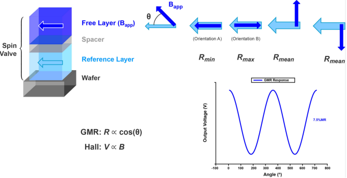
Figure 1: Giant magnetoresistance response
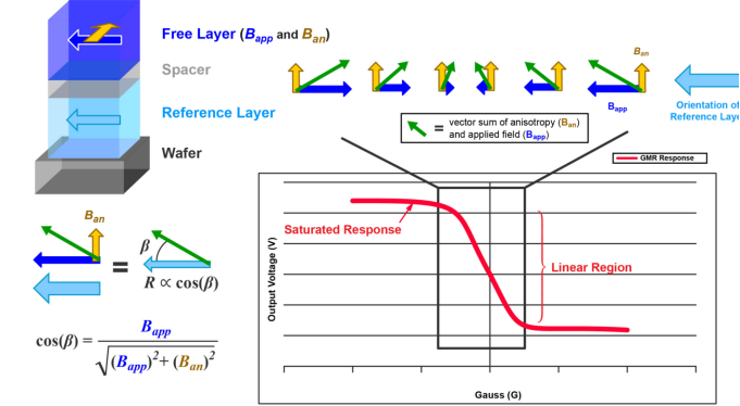
Figure 2: Response linearization when anisotropy is introduced.
Sensor IC using giant magnetoresistance technology
Typically, a giant magnetoresistance resistor needs to be created and placed in a Wheatstone bridge configuration. Half of the Wheatstone bridge (elements A and C in Figure 3) is under one magnetic field and the other half of the Wheatstone bridge (elements B and D) is under another magnetic field. Ideally, these conditions exhibit an equal but opposite response, maximizing the output of the Wheatstone bridge. As shown by the blue arrows and text in Fig. 3, elements A and C sense the magnetic field in the left direction (in this example, the anti-parallel state, which is represented as Rmax in Fig. 1), and the elements B and D are in the right direction. (Parallel state in this example, denoted as Rmin in Fig. 1) The magnetic field is sensed. The result is that resistors A and C will be in a high resistance state and the resistors in B and D will be in a low resistance state. The differential output will be positive.
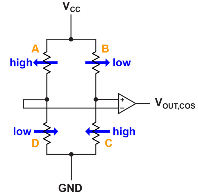
Figure 3: Wheatstone Bridge.
When using a Wheatstone bridge, the output is always proportional to the applied VCC, and the midpoint of the differential output is 0V without the application of a magnetic field. The differential bridge output swings either positively or negatively according to the direction in which the Wheatstone bridge applies the magnetic field. This bridge configuration eliminates temperature drift and isolates stray magnetic fields to some extent.
For current sensors, the magnetic field changes in the same direction at elements A and C, while maintaining the opposite direction at elements B and D (see Figure 4). The output of the Wheatstone bridge is fed to a differential amplifier, which is then passed through Allegro's commonly used sensitivity and offset correction circuitry, perhaps further through analog or digital domain advanced signal processing circuitry. In other applications where there is no integrated conductor, the physical spatial distance of the giant magnetoresistive element can be used to influence the differential signal to achieve response to various magnetic excitations.
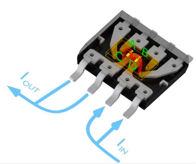
Figure 4: Giant magnetoresistance and current sensing.
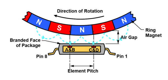
Figure 5: Giant magnetoresistance and ring magnet applications.
Another application for giant magnetoresistance is for ring magnet speed sensing applications such as ABS or gearbox sensors. As shown in Figure 5, alternating north and south pole magnetization is used to form the annular magnetic material. A giant magnetoresistive sensor can be placed underneath the material to level the chip. The spacing between the giant magnetoresistive elements A and C and B and D forms a different magnetic field, and the magnetic field is sensed by these element groups according to the position of the ring magnet at its rotation period. When N (north) is at the center above the chip, the magnetic field points to the left side above elements A and C, and to the right side above elements B and D. This will produce a response in the giant magnetoresistance (as shown in Figure 3), and the giant magnetoresistive bridge produces the largest positive response. When above the S (south) pole, the response will be the largest negative value. While between the poles, the fields of each element are approximately equal and the response of the bridge is close to zero. This will result in a sinusoidal output of the sensor as the ring magnet rotates. The velocity of the ring magnet can be determined by measuring the time between output thresholds over a period of time.
Compared with traditional Hall sensors, giant magnetoresistance technology ensures high sensitivity and high uniformity in a larger air gap, thus ensuring high-precision speed measurement.
Allegro's monolithic giant magnetoresistive solution
Many giant magnetoresistive solution vendors use multi-chip solutions, including sensor chips and interface chips. Allegro is one of the few IC manufacturers that can directly integrate giant magnetoresistance technology on top of semiconductor wafers.
This highly integrated technology has many advantages, including no additional chip-to-chip interface bonding, improved reliability, and simplifies the overall design when integrating current-carrying lines or when the components need to be positioned relative to an external reference.
Because Allegro's giant magnetoresistive solution is essentially monolithic, the giant magnetoresistive IC wafer is managed the same as the Hall effect sensor IC wafer. The fabricated wafer is placed to a thickness suitable for its package and the wafer is cut to the appropriate chip size. After this step, the device is packaged in the Allegro family of standard semiconductor ICs.
in conclusion
Giant magnetoresistive sensors have some advantages over Hall effect sensors. However, it is very important to understand the application requirements faced by these sensors, as Hall solutions are more suitable in many cases. Allegro's new highly integrated giant magnetoresistive technology offers designers more options to meet the needs of new applications and extend the capabilities of existing applications. Giant magnetoresistance technology improves signal-to-noise ratio, improves resolution, and reduces the level of magnetic field required for a given solution (allowing for smaller magnets, larger air gaps, etc.). In addition, sensing in the plane of the wafer or IC surface enables a new, differential magnetic solution that is more reliable than planar Hall sensing technology. Allegro will leverage the new capabilities offered by giant magnetoresistance technology to introduce a broader portfolio of magnetic sensor ICs.