Collect
Industrial
 Navigateㄩ
What is a Hall sensor? What is the application of the Hall sensor in the anti-pinch system of the electric window?
The Hall sensor is a magnetic field sensor fabricated according to the Hall effect. The Hall effect is a kind of magnetoelectric effect, which was discovered by Hall (A.H. Hall, 1855-1938) in 1879 when studying the conductive mechanism of metals. Later, it was found that semiconductors, conductive fluids, etc. also have this effect, and the Hall effect of semiconductors is much stronger than that of metals. Various Hall elements made by this phenomenon are widely used in industrial automation technology, detection technology, information processing, etc. aspect. The Hall effect is the basic method for studying the properties of semiconductor materials. The Hall coefficient measured by the Hall effect experiment can determine important parameters such as conductivity type, carrier concentration, and carrier mobility of the semiconductor material.
introduction
With the advancement of modern automotive electronics technology, the traditional parts and assemblies in automobiles are also developing towards mechatronics. The large number of electronic devices used in automobiles not only improve the comfort of the car, but also put forward new requirements for the safety of the car. In order to facilitate the driver and passengers, a large number of cars use electric windows, and many electric windows do not have anti-pinch function, which is easy to cause damage to occupants, especially children. For safety reasons, it is absolutely necessary to develop a window control module with anti-pinch function.
The anti-pinch design of this paper combines the detection of the motor speed and the detection of motor current changes by the Hall sensor to realize the anti-pinch function. This solution avoids the defects that the window anti-pinch system is susceptible to the external environment and ensures the anti-pinch effect is reliable. The cost is lower, and it is not necessary to change the production process of the traditional door. When the old model of the electric window without the anti-pinch function is modified, the mechanical structure and circuit structure of the currently formed automobile door can be changed without replacing the electric window lifting. The controller is very convenient.
1 electric window anti-pinch design
During the normal rise of the electric window, when an object is clamped at any position, the controller will immediately stop the rising action and automatically return to the bottom dead center, and then immediately stop the power to stop, to release the object, the protection department Safety of personnel (especially children under 6 years old).
At the top and bottom dead center position, regardless of whether the lift switch is released, the controller will automatically power off to avoid the motor burning due to long-term stall. If the mechanical window of the power window is stuck, the controller will immediately power off, effectively protecting the motor from burning.
The anti-pinch controller not only increases the safety of the car, but also improves the grade of the car, and also greatly extends the service life of the electric window.
Our anti-pinch controller abandons CAN/LIN bus technology, and each door is independently controlled and does not affect each other. Because the biggest advantage of the CAN/LIN bus is that there are only 2/1 wires, which can reduce wiring, but this is also a fatal shortcoming. If any place is short-circuited, the whole system will be completely paralyzed.
1.1 Determination of the position of the window
The rotation of the window control motor drives the movement of the wire rope, thereby controlling the up and down movement of the window. During the movement of the window, the number of turns of the motor is proportional to the moving distance of the window. When the rotor of the motor rotates for one week, the Hall sensor generates a square wave pulse signal. When the window is raised from the lowest position to the top, the pulse signal output by the Hall sensor can be counted by the MCU, from the bottom to the top of the window, and it is repeated three times up and down, and the average value nth is taken as the calibration. The benchmark is recorded in the E2PROM. After that, the software control starts from the bottom position of the window (this time is manual control, the window runs to the bottom, the motor is blocked), and the count starts from zero, and the rising process counts up according to the current count value. The descending process counts down based on the current count value. Therefore, the current position of the window can be determined in real time by the pulse output and counting scheme of the Hall sensor, and whether the window is in the anti-pinch area according to the provisions of European 74/60/EEC and the US FMVSSll8 standard. For this system, the error of pulse counting during measurement is negligible, and the error that may be caused in long-term operation can be solved by means of periodic calibration.
1.2 Determination of anti-pinch scheme
The system uses the method of detecting the armature current of the motor to determine whether the window encounters an obstacle during the ascent process. The solution should solve the following problems in the specific implementation process:
(1) Determine the anti-pinch area and the window position. According to the European 74/60/EEC and the US FMVSSll8 standard, the corresponding anti-pinch area and window position are determined.
(2) Determination of the motor armature current threshold ith during anti-clamping, that is, after the current value rises to the set threshold value in the anti-pinch area, it is considered that an obstacle is encountered, and the window anti-clamp function is activated. The problem here is that the window button has just been pressed (either rising or falling), when the window motor has just started, because the back electromotive force of the motor has not been established, the current will have a large amplitude for a short time. The current amplitude is often larger than the set anti-pinch current threshold, and it is necessary to make such a large current amplitude and encounter obstacles during the window rise. After the window motor starts 50 ms delay, the current detection is performed, which can avoid the influence of the instantaneous overshoot of the current on the anti-pinch current threshold setting. In the actual design, a central controller that can be used for diagnostic functions is used, and the USB-CAN200 tool produced by Wuhan Jiyang Solar Power Co., Ltd. is used to feed back the data in the running process to the PC, present in Excel form, and draw graphics. Then, the threshold ith is conveniently determined, and an appropriate threshold is determined by running the test multiple times.
(3) Selection of MCU and power drive devices. The anti-clamping scheme involves more real-time detection and real-time calculation, which requires the MCU to have higher computing power. The software implementation in the solution is based on the transplantation of 米C/OS-II real-time operating system solution, so it is popular in European car systems. The higher Infineon XCl64CS MCU, the power driver chip selects the BTS781 chip with fault diagnosis function.
2 anti-pinch system hardware design
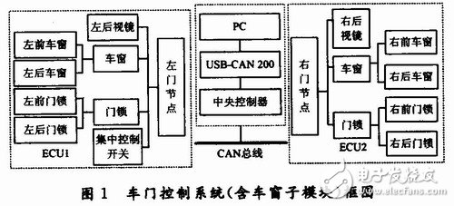
The door control system includes two parts: the electric window control system and the electric rearview mirror control system. The anti-pinch electric window is a sub-module of the door control system. In the whole door control system, a ※general distribution, partial concentration is adopted. "Control" scheme, as shown in Figure 1. The control of the front and rear doors is used as an ECU module. The control of the front and rear doors is used as another ECU module. The two modules and the module and the central controller are connected by CAN bus.
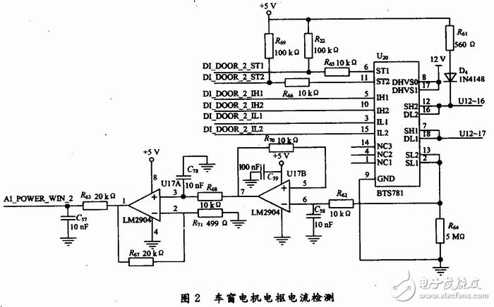
The anti-trap system hardware design uses BTS781 as the core, and connects the ST1, ST2, IH1, IH2, IL1, IL2 ports and the microcontroller XCl64CS chip to receive the commands from the microcontroller to control the lifting of the window. The motor armature current is detected by serially connecting a 5 m次 resistor R37 to pins 2 and 13 of the full-bridge driver chip BTS781. After low-pass filtering and amplification, it is sent to the A/D port of the MCU for sampling. Figure 2 shows.
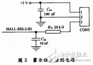
The position measurement of the window is realized by means of the Hall sensor output pulse count. The Infineon TLE4923 Hall sensor is used to directly output the square wave signal. After low-pass filtering, the pulse signal is input into the MCU to count it, thereby determining the current position of the window, as shown in FIG.
3 software design
The software design of the system should not only consider the convenience of control, but also consider the scalability of future functions. Therefore, the software design of the system is based on the real-time operating system, that is, the 米C/OS-II real-time operating system kernel is first transplanted to the XCl64CS MCU, and then the anti-pinch window control is added in the manner of one of the tasks.
3.1 米C/OS-II real-time operating system kernel porting
The porting is to port the 米C/OS-II real-time kernel to the XCl64CS microcontroller. Since 米C/OS-II can only be implemented in assembly language when reading and writing processor registers, some processor-related code is written in assembly language, but most 米C/OS-II code is written in C language. The migration work mainly makes 米C/OS-II correctly define and use XCl64C-S. Please refer to the article written by the author of this article for details, which will not be repeated here.
3.2 Anti-pinch electric window software design
After the 米C/OS-II real-time operating system is transplanted on the designed hardware platform, the anti-pinch power window control is added in the task mode, and the anti-pinch function is implemented with reference to the previous contents. The flow chart is shown in FIG. 4 .
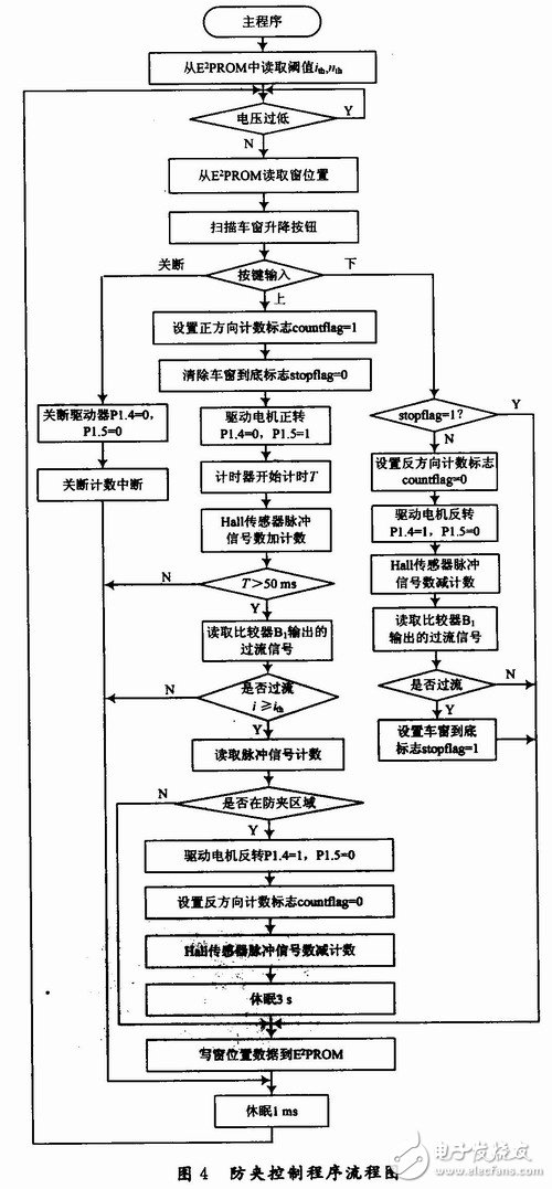
When the controller XCl64CS is powered on, the initial data such as nth, ith, etc. are read from the E2PROM, and the power supply voltage is detected. When the voltage value is stable, the position of the window stored in the E2PROM is read, and then the key input is read, if there is a lift truck For window operation, the corresponding switch signal is set to drive the MOS transistors T1, T2, T3, T4 in the chip BTS781. If the window moves upwards, the timer starts to count, the Hall sensor pulse signal is counted, and after 50 ms delay, the current value is detected to be overcurrent. If an overcurrent signal is detected during the window rise, that is, the window motor If the current value is greater than the current threshold ith, and the window position is in the anti-pinch start region, it is determined that the window is blocked, and the controller outputs the direction switch signal, and the motor is reversed by the MOS tube T1, T2, T3, T4 for 1 s. Stop and the anti-pinch operation is completed. Regardless of the motor's lifting movement, the controller records the number of pulse signals of the Hall sensor through the counting program, thereby determining the relative position of the window and writing the position information to the E2PROM when needed.
4 test
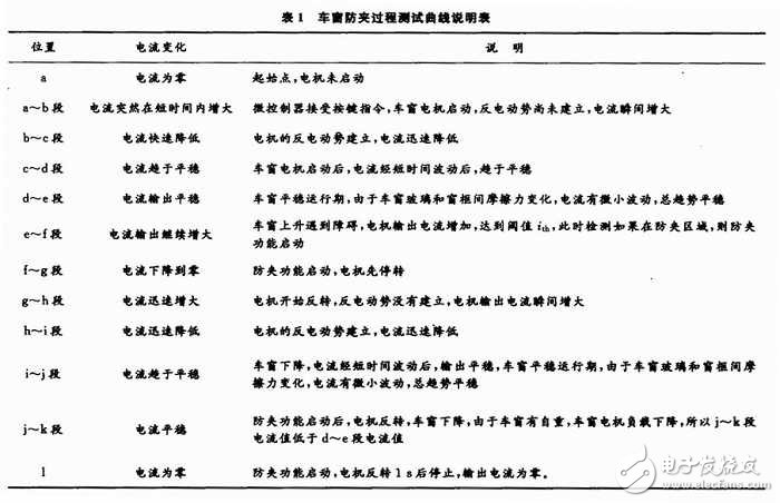
After completing the hardware production and programming of the software, a test bench was produced. After testing the gantry, the test results shown in Figure 5 are obtained. The test results are plotted on the Excel chart and the graph on the upper right side of Figure 5. The current change curve actually measured by the oscilloscope is shown in the lower right curve of Figure 5. The figure shows. The actual test curve change of the oscilloscope is shown in Table 1.
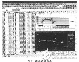
As can be seen from Figure 5, the test results are drawn in the same pattern as the actual test pattern of the oscilloscope to achieve the desired anti-pinch effect.
5 Conclusion
The anti-pinch design of electric window is expounded, and the anti-pinch function of the window is realized without changing the original installation structure. The key is to design a suitable current detection threshold. In this study, the current threshold is given based on the experiment, and a test bench is fabricated. The test results show that the design made in this paper can achieve reliable window anti-pinch function.
PreㄩCurrent sensor wiring 2026-06-14
NextㄩWireless sensors improve motion of amputees 2026-06-14