Collect
Industrial
 NavigateŁş
Current sensor wiring
The Hall current sensor is a sensor that converts a large current into a secondary minute voltage signal by using the Hall effect.
Hall current sensors have been widely used in frequency control devices, inverter devices, UPS power supplies, inverter welding machines, electrolytic plating, CNC machine tools, microcomputer monitoring systems, power grid monitoring systems, and various fields where isolation and detection of current and voltage are required. .
Hall current sensors are a very common sensor in our daily life, and are widely used in household appliances, smart grids, electric vehicles, wind power generation, and so on. As a high-tech product, it has a unique current sensor wiring method.
The wiring method of the current sensor is divided into:
1, one-phase wiring, used to measure the current of one phase or three phases (through the transfer switch).
2, incomplete star connection, also known as V-shaped wiring, used to measure the load current or unbalanced three-phase three-wire current sensor line current, 6-10KV neutral point ungrounded system is widely used, not complete star connection The relay protection circuit can protect various phase-to-phase short circuits, but the sensitivity is poor compared with the three-phase star connection, but the use of one transformer reduces the cost.
3, differential wiring, usually used in relay protection lines, such as line or motor protection and capacitor cross-link differential protection, it can reflect various phase-to-phase short circuit.
4, star connection, measuring the three-phase current of the load balance or unbalanced three-phase power system, this wiring mode has the same sensitivity to three-phase, two-phase short circuit and single-phase ground short circuit, and the reliability is high.
The magnetically compensated current sensor is an advanced high-tech modular current sensor that isolates the main circuit from the control loop and detects sinusoidal and non-sinusoidal current values from DC to 100 kHz. The secondary side can truly reflect the primary side. Waveform.
The principle of magnetic compensation current sensor:
According to Ampere's law, the primary measured voltage U1 is converted into I1 by serially connecting the current limiting resistor R1, and I1N1 will generate the magnetic field B1, and magnetically compensated by the magnetic field B2 generated by I2N2 to maintain the magnetic equilibrium state, that is, I1N1=I2N2, so I2=I1N1N2, when N1/N2 is determined, I2 is proportional to I1, and I2 is converted into a voltage output signal by Rm.
Application of magnetic compensation current sensor:
Magnetically compensated current sensors in the field of microcomputer monitoring of power systems, new inverters, rectifiers, industrial automation control, welding equipment, AC frequency converters, safety power supplies, railway signal monitoring, railway locomotives, CNC machine tools, trolley buses, etc. Get a wide range of applications.
AC two-wire type: directly connected to the control loop, one power supply, one load
AC multi-line type: two connected power supply two load, it depends on whether it is normally open or normally closed, that is, two control lines of two power lines, and some are long open and long closed.
DC two-wire type: black to [or blue] negative red [or brown] to load
DC three-wire type: PNP and NPN type, black to [or blue] negative red [or brown] to positive, color [or black] to load, and a long open and long closed PNP feedback positive NPN feedback negative .
Commonly used in these several ways:
1 pin: Negative power (-15V) positive power input
2 feet: power ground (OV) ground wire
3 feet: positive power (15V) negative power input
4 feet: Output measurement signal output
5, 7 feet: primary current input input current of the measured object
6, 8 feet: secondary primary current output output current of the measured object
Hall current sensor wiring diagram
(1) The direct-inspection (no amplification) current sensor wiring diagram is shown in Figure 1-7.
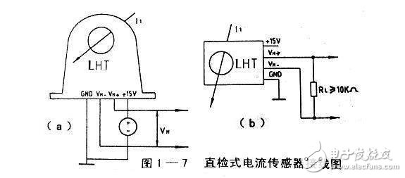
(a) The figure is a P-type (printer pin type) connection, (b) is a C type (socket plug type) connection, and VN. and VN represent a Hall output voltage.
(2) The wiring diagram of the direct-inspection amplified current sensor is shown in Figure 1-8.
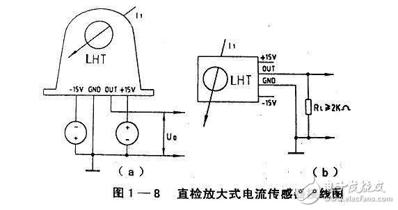
(a) The figure is a P-type connection, and (b) is a C-type connection. In the figure, U0 represents an output voltage, and RL represents a load resistance.
(3) The wiring diagram of the magnetic compensation current sensor is shown in Figure 1-9.
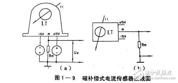
(a) The figure is a P-type connection, and (b) the figure is a C-type connection (note that the third pin of the four-pin socket is an empty foot)
The plate pin connection of the above three sensors is the same as the physical arrangement method, and the socket plug connection method is also consistent with the physical arrangement method to avoid wiring errors. In the above Hall current sensor wiring diagram, the main circuit measured current I1 has an arrow in the perforation indicating the positive direction of the current, and the physical casing also indicates the positive direction of the current. This is the current sensor that specifies the current of the measured current I1. The positive direction is the same polarity as the output current I2. This is critical in three-phase AC or multi-channel DC detection.