Collect
 NavigateŁş


Discontinued part:UDN2936 Replace by A3936SED.PDF download!
 DescriptionŁş
 print
print
 telŁş0755-83031813
 emailŁşsumzi@sumzi.com


- Production
- Technology
- Configuration
- Download
ProductionŁş

Combining logic and power, the UDN2936W-120 provides com-
mutation and drive for three-phase brushless dc motors. Each of the
three outputs are rated at 45 V and ˇŔ2 A (ˇŔ3 A peak), and include
internal ground clamp and flyback diodes. The driver also features
internal commutation logic, PWM current control, and thermal shut-
down protection.
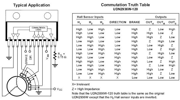
The UDN2936W-120 is compatible with single-ended digital or
linear Hall effect sensors. The commutating logic is programmed for
120ˇă electrical separation. The UDN2936W-120 can replace the
original UDN2936W (60ˇă electrical separation) by simply adding an
inverter at the H2 input. Current control is accomplished by sensing
current through an external sense resistor and pulse-width modulating
the source drivers. Voltage thresholds and hysteresis can be externally
set by the user. If desired, internal threshold and hysteresis defaults
(300 mV, 7.5 percent) can be used. The UDN2936W-120 also includes
braking and direction control. Internal protection circuitry prevents
crossover current when braking or changing direction.
The UDN2936W-120 is also available for operation between -40ˇăC
and +85ˇăC. To order, change the prefix from ˇ®UDNˇŻ to ˇ®UDQˇŻ.
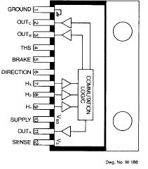
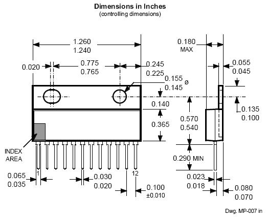
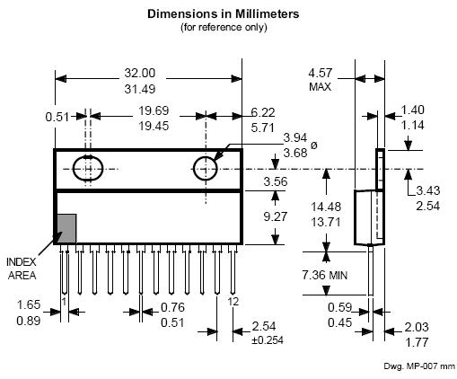
For maximum power-handling capability, the UDN2936W-120 is
supplied in 12-pin single in-line power-tab package. An external heat
sink may be required for high-current applications. The tab is at
ground potential and needs no insulation.
FEATURES
ˇö 10 V to 45 V Operation
ˇö ˇŔ3 A Peak Output Current
ˇö Internal Clamp Diodes
ˇö Internal PWM Current Control
ˇö 120ˇă Commutation Decoding Logic
ˇö Thermal Shutdown Protection
ˇö Compatible with Single-Ended or Differential Hall-Effect Sensors
ˇö Braking and Direction Control
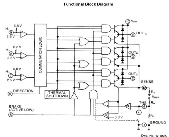
The UDN2936W-120 power driver provides commutation
logic and power outputs to drive three-phase brushless dc
motors.
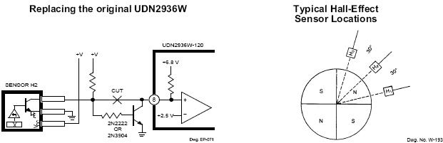
The UDN2936W-120 is designed to interface with single-
ended linear or digital Hall-effect devices (HEDs). Internal
pull-up resistors allow for direct use with open-collector digital
HEDs. The Hn inputs have 2.5 V thresholds.
The commutation logic provides decoding for HEDs with
120ˇă electrical separation. At any one step in the logic sequenc-
ing, one half-bridge driver is sourcing current, one driver is
sinking current, and one driver is in a high-impedance state (see
Truth Table).
A logic low on the BRAKE pin turns on the three sink
drivers and turns off the three source drivers, essentially
shorting the motor windings to ground. During braking, the
back-electromotive force generated by the motor produces a
current that dynamically brakes the motor. Depending upon the
rotational velocity of the motor, this current can approach the
locked rotor current level (which is limited only by the motor
winding resistance). During braking, the output current-
limiting circuitry is disabled and care should be taken to ensure
that the back-EMF generated brake current does not exceed the
maximum rating (3 A peak) of the sink drivers and ground
clamp diodes.
Changing the logic level of the DIRECTION pin inverts the
output states, thus reversing the direction of the motor. Chang-
ing the direction of a rotating motor produces a back-EMF
current similar to when braking the motor. The load current
should not be allowed to exceed the maximum rating (ˇŔ3 A
peak) of the drivers.
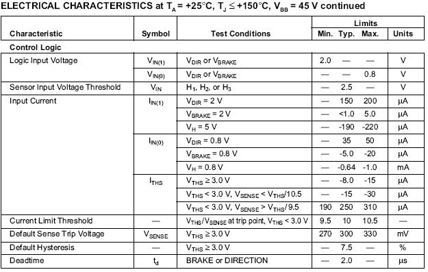
An internally generated dead time (td) of approximately
2 µs prevents potentially destructive crossover currents that can
occur when changing direction or braking.
Motor current is internally controlled by pulse-width
modulating the source drivers with a preset hysteresis format.
Load current through an external sense resistor (RS) is con-
stantly monitored. When the current reaches the set trip point
(determined by an external reference voltage or internal
default), the source driver is disabled. Current recirculates
through the ground clamp diode, motor winding, and sink
driver. An internal constant-current sink reduces the trip point
(hysteresis). When the decaying current reaches this lower
threshold, the source driver is enabled again and the cycle
repeats
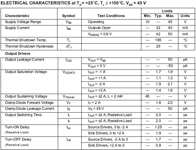
Thresholds and hysteresis can be set with external resistors,
or internal defaults can be used. With VTHS > 3.0 V, the trip
point is internally set at 300 mV with 7.5% hysteresis. Load
current is then determined by the equation:
ITRIP = 0.3 / RS
With VTHS < 3.0 V, the threshold, hysteresis percentage,
and peak current are set with external resistors according to the
equations:
threshold voltage (VTHS) = VREF x RT /(RH + RT)
hysteresis percentage = RH/50 VREF
load trip current (ITRIP) = VTHS/10 RS
Percentage hysteresis is a fixed value independent of load
current. The chopping frequency is a function of circuit
parameters including load inductance, load resistance, supply
voltage, hysteresis, and switching speed of the drivers.
The UDN2936W-120 outputs are rated for normal operat-
ing currents of up to ˇŔ2 A and startup currents to ˇŔ3 A (see
cautions above regarding braking and changing of motor
direction). Internal power ground-clamp and flyback diodes
protect the outputs from the voltage transients that occur when
switching inductive loads. All devices also feature thermal
protection circuitry. If the junction temperature reaches
+165ˇăC, the thermal shutdown circuitry turns off all output
drivers. The outputs are re-enabled when the junction cools
down to approximately +140ˇăC. This protection is only
intended to protect the device from failures due to excessive
junction temperature or loss of heat sinking and should not
imply that output short circuits are permitted.
As with all high-power integrated circuits, the printed
wiring board should utilize a heavy ground plane. For optimum
performance, the drivers should be soldered directly into the
board. The power supply should be decoupled with an electro-
lytic capacitor (>10 µF) as close as possible to the device
supply pin (VBB).
Replacing the UDN2936W. The original UDN2936W can
be easily replaced with a UDN2936W-120 by inserting an
inverter (two resistors and a 2N3904 or 2N2222) between the
H2 Hall sensor and pin 8 of the UDN2936W-120, as shown in
the figure on the next page. If an extra inverter is available, be
certain that a pull-up for the Hall sensor is provided.
Contact person:
Frances New
Phone:+86-755-81832961
Fax:+86-755-83299282
Email:sumzi@sumzi.com
MSN:sumzi_frances@msn.com
http://www.sumzi.com