 ЪеВиБОеО
 ЕБЧАЮЛжУЃК
L297 ММЪѕзЪСЯМАБЈМлЃЈИНPDFЮФЕЕЃЉ
DATASHEET PDF L297.pdf
DESCRIPTION
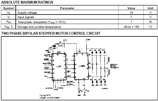
The L297/A/D Stepper Motor Controller IC gener-
ates four phase drive signals for two phase bipolar
and four phase unipolar step motors in microcom-
puter-controlled applications. The motor can be
driven in half step, normal and wawe drive modes
and on-chip PWM chopper circuits permit switch-
mode control of the current in the windings. Afeature of this device is that it requires only clock,
direction and mode input signals. Since the phase
are generated internally the burden on the micro-
processor, and the programmer, is greatly reduced.
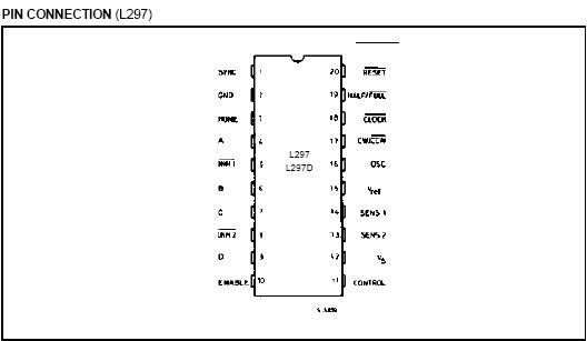
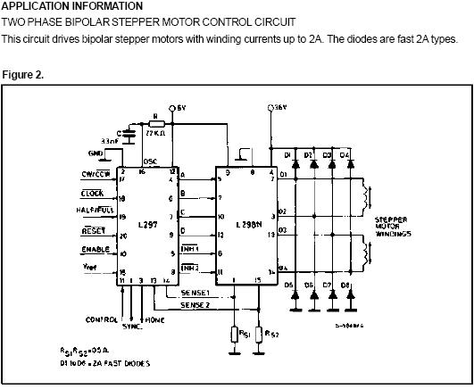
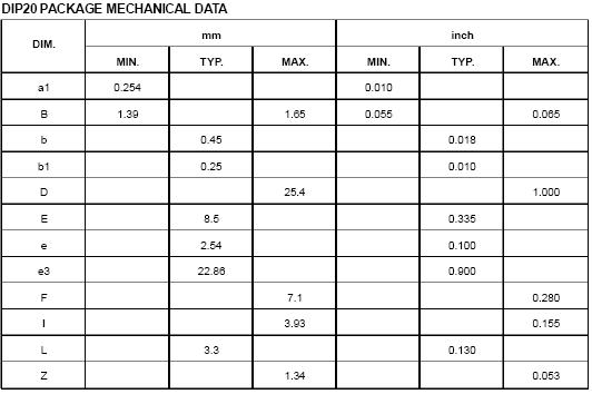
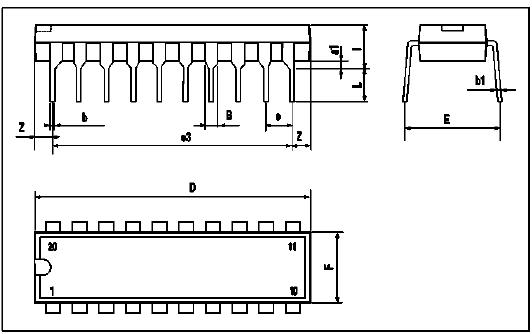
Mounted in DIP20 and SO20 packages, the L297
can be used with monolithic bridge drives such as
the L298N or L293E, or with discrete transistors
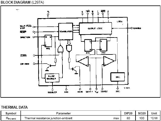
CIRCUIT OPERATION
The L297(A) is intended for use with a dual bridge
driver, quad darlington array or discrete power de-
vices in step motor driving applications. It receives
step clock, direction and mode signals from the
systems controller (usually a microcomputer chip)
and generates control signals for the power stage.
The principal functions are a translator, which gen-
erates the motor phase sequences, and a dual
PW/M chopper circuit which regulates the current
in the motor windings. The translator generates
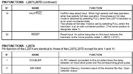
three different sequences, selected by the
HALF/FULL input. These are normal (two phases
energised), wave drive (one phase energised) and
half-step (alternately one phase energised/two
phases energised). Two inhibit signals are also
generated by the L297 in half step and wave drive
modes. These signals, which connect directly to the
L298ЁЏs enable inputs, are intended to speed current
decay when a winding is de-energised. When the
L297 is used to drive a unipolar motor the chopper
acts on these lines.
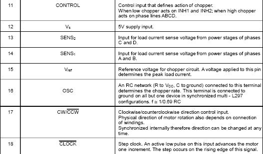
An input called CONTROL determines whether the
chopper will act on the phase lines ABCD or the
inhibit lines INH1 and INH2. When the phase lines
are chopped the non-active phase line of each pair
(AB or CD) is activated (rather than interrupting the
line then active). In L297 + L298 configurations this
technique reduces dissipation in the load current
sense resistors.
A common on-chip oscillator drives the dual chop-
per. It supplies pulses at the chopper rate which set
the two flip-flops FF1 and FF2. When the current in
a winding reaches the programmed peak value the
voltage across the sense resistor (connected to one
of the sense inputs SENS1 or SENS2) equals Vref
and the corresponding comparator resets its flip
flop, interrupting the drive current until the next
oscillator pulse arrives. The peak current for both
windings is programmed by a voltage divider on the
Vref input.
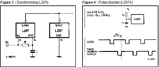
Ground noise problems in multiple configurations
can be avoided by synchronising the chopper oscil-
lators. This is done by connecting all the SYNC pins
together, mounting the oscillator RC network on
one device only and grounding the OSC pin on all
other devices.
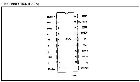
The L297A includes a pulse doubler on the step
clock line which is intended to simplify the imple-
mentation of multiple stepping. A ghost pulse is
generated automatically after each input pulse, de-
layed by the time 0.75 RdCd.
The RC network should be dimensioned to place
the ghost pulse roughly halfway between clock
pulses. If pin 1 (DOUBLER) is grounded the doubler
function is disabled.


ЩЯвЛЦЊЃКL293 ММЪѕзЪСЯМАБЈМл(ИНPDFЮФЕЕ) 2026-06-13
ЯТвЛЦЊЃКL298 ММЪѕзЪСЯМАБЈМлЃЈИНPDFЮФЕЕЃЉ 2026-06-13


